433MHz Wireless Irrigation Controller
433MHz Smart Irrigation Controller 2km Radio based Wireless Solenoid Vlave Controller 2 Channels Valve
Introduction
LS-SVC02 is a radio based solenoid latching valve controller. It has built-in power charge circuit. Adding a lithium battery, you could use solar power supply. LS-SVC02 is OK to control 2 stations 12V solenoid latching valves and connect 3 sensors(4-20mA). Our irrigation systems are ideal for commercial/municipal applications such as farmland, orchard, street and highway landscaping, medians, parks, construction sites.
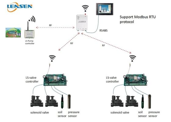
Application diagram for reference
This system includes a master (LS-R324 wireless DTU) and a pump controller (LS-RDIO0202 wireless RTU) and some electric valve controllers (LS-SVC02).
You could connect LS-R324 wireless DTU to HMI, PC software or PLC via RS485 port. We support Modbus RTU protocol. Through programming your controller, you could realize remote control your main pump ON-OFF and electric valves ON-OFF automatically.

System requirements
All wireless devices in the same system should use the same frequency channel, with the same baud rate, then they can communicate with each other. Before using, please check channel and ID setting first. You could use the DIP to set channel and ID (please refer DIP setting part)
Solenoid Valve Controller’s Parameter
RF parameter: 433MHz, 1W power output for 2km LOS wireless control, 9600bps , TTL interface
Power supply: 12V DC. We have built-in solar charge circuit. You could use solar panel+lithium battery to supply power for this board.
Battery type: 12V DC lithium Ion battery. Our charge circuit is based on 3S Lithium Ion battery. Lithium Ion nominal voltage is 3.6V – 3 x 3.6 = 10.8V, Lithium Ion full power is 4.2V - 3x4.2=12.6V. We recommend to use 12V, 10Ah battery. You could choose proper battery capacity according your actual application requirements.
Solar panel: we recommend to use 18V, 30W solar panel. You could choose proper one according your local sunshine condition.
Electric valve: we can drive 2 stations of 9-36V DC type solenoid latching valves.
How to connect
How to connect 2-wire battery

According to the above picture, you could connect 2 solenoid latching valves, 3 sensors (4-20mA analog input), 2 flow switches(digital input) to this controller. Please connect valves and sensors like the picture shows. AI and DI are passive inputs. Connect battery and solar panel correctly.
Note: If you use two wire battery, please make sure jumper cap 1 short connects with jumper cap 2 and jumper caps 3 connects with jumper cap 4.
Power LED
Power LED is to indicate wireless module’s working condition. When wireless module is waked up for data receiving and data transmitting, the LED will be On red. When wireless module is in sleep, the LED is OFF, at this mode, it can not transmit or receive data.
RF LED
RF LED is on wireless module. When data transmitting, Red LED blinks, when data receiving, blue LED blinks.
How to connect 4-wire battery

Please refer the wiring diagram above.
If you use four-wire battery, jumper caps don’t need short connect.
About the DIP setting
a. DIP for channel
DIP 1-4 is for channel setting
DIP1 ON =20 =1
DIP2 ON =21 =2
DIP3 ON =22 =4
DIP4 ON =23 =8
DIP 5-8, no definition now, please keep them OFF
This valve controller has 15 channels totally, please refer this setting table
| Channel No. |
DIP Setting |
Channel No. |
DIP Setting |
Channel No. |
DIP setting |
Channel No. |
DIP setting |
| 1 |

1234
|
2 |

1234
|
3 |

1234
|
4 |

1234
|
| 5 |

1234
|
6 |

1234
|
7 |

1234
|
8 |

1234
|
| 9 |

1234
|
10 |

1234
|
11 |

1234
|
12 |

1234
|
| 13 |

1234
|
14 |

1234
|
15 |

1234
|
|
|
DIP1 ON =20 =1
DIP2 ON =21 =2
DIP3 ON =22 =4
DIP4 ON =23 =8
DIP5 ON =24 =16
DIP6 ON =25 =32
DIP7 ON =26 =64
DIP8 ON =27 =128
The ID is controller’s local ID, also Modbus communication ID, please refer this table
| ID |
DIP location |
ID |
DIP location |
ID |
DIP location |
| 1 |
  |
2 |
  |
3 |
  |
| 4 |
  |
5 |
  |
6 |
  |
| 7 |
  |
8 |
  |
9 |
  |
| 10 |
  |
11 |
  |
12 |
  |
| 13 |
  |
14 |
  |
15 |
  |
| 121 |
  |
122 |
  |
123 |
  |
| fertilizer |
  |
pump |
  |
|
|

 Your message must be between 20-3,000 characters!
 Please check your E-mail!
  Your message must be between 20-3,000 characters!
 Please check your E-mail!


