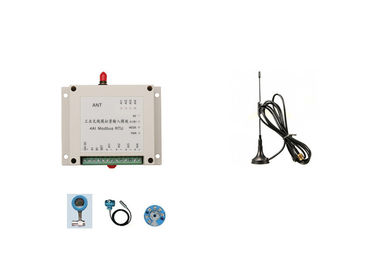
Power Output: | 1W | Channels: | 4AI |
---|---|---|---|
Input Type: | 0-5V Or 4-20mA Or 0-10V | Distance: | 2km |
Receiver Side: | 4AO | Frequency: | 433MHz |
High Light: | 1W Wireless Analog Transmitter,4-20mA Wireless Analog Transmitter,2km Analog Input Module |
Wireless Analog Input Module 4-20mA Signal Wireless Transmission Modbus RTU
Character
LS-RAI04 4 channels analog input module
4 channels 4-20mA signal wireless transmission to PLC
0-5V analog signal wireless transmission
0-10V analog signal wireless transfer
2km wireless control in industry automation area
Lensen Wireless RTU features
- Portable device, DIN-rail mounting for easy installation
- Isolated inputs
- LEDs for power supply, communication, input, output status
- Flexible networking, point to point or point to multipoints
- DIP to change different modes
- Different types of I/O, DI, DO, AI, AO are available
- I/O expandable
- Short delay time
- Easy handing on RS485 network, support Modbus RTU protocol
- Support on-line upgrade. Can configure by customer in setting mode
Paramaeters
Frequency | 433MHz or 450MHz or 470MHz or 868MHz/915MHz or 4G |
Power output | 1W |
Products | 4AI |
Input type | 4-20mA or 0-5V or 0-10V |
Output type | 4-20mA or 0-5V or 0-10V |
Resolution ratio | 24 bit |
Accuracy | ±0.02% |
Power supply | 9-36V DC usually use 24V DC |
Interface | RS-485 |
Channel No. | 15ch default, can program via DIP switch |
Antenna | Sucker antenna with 1.5m cable |
Working temperature | -35 °C~+75 °C industrial |
Working humidity | 10%-90% relative humidity, no condensation |
Dimension | 115×90×40(mm) |
Fix way | Standard 3.5 inch industrial DIN guild rail |
Advantage of wireless solution
- No wires to bury or maintain, no need to drill holes on wall
- Reliable communication in all direction,any terrain, regardless of hills, walls, trees
- Cost saving in installation and maintenance
- Radio/Lora based, no need internet and monthly fee, full ownership of the system
- 4G based, high speed, no distance limit
Modbus RTU communication and corresponding value
Register types:
Register types | Read command |
Write command |
Power off | Function |
Hold register | 0x01 |
Input --not support |
Not keep | Can read input value |
0x03 |
A. Hold register
1. Analog input value: 0x0008~0x000B
2. Analog output value: 0x0048~0x004B
B: How to read
Hold register: can read 4 analog input or control 4 analog output at one time
Register control way
AI/AO | IC |
Read/ |
Function ID | items support | ||
No. | IC Type | PLC ID | Modbus ID | |||
AI1 | Hold register | 40009 | 8 | Read | 03 | 2AI/4AI |
AI2 | Hold register | 40010 | 9 | Read | 03 | |
AI3 | Hold register | 40011 | 10 | Read | 03 | 4AI |
AI4 | Hold register | 40012 | 11 | Read | 03 | |
AO1 | Hold register | 40073 | 72 | Read/write | 03/06 | 2AO/4AO |
AO2 | Hold register | 40074 | 73 | Read/write | 03/06 | |
AO3 | Hold register | 40075 | 74 | Read/write | 03/06 | 4AO |
AO4 | Hold register | 40076 | 75 | Read/write | 03/06 |
About value calculation
Analog input
Our analog module’s max measure range value is : 0X7FFF
1. Directly measure current and voltage
Exact value=value you read/0x7FFF*max range
For example: to read the 1st passage of module’s (with max range of 0-20mA) input value
Register 0x0008(analog input of the 1st passage)
Feedback: 0x3801
Current value: (0x3801/0x7FFF)*20mA=8.7509mA
2. To measure sensor’s value(4-20mA, 0-6 meter level sensor)
If feedback value is less than 6554, level value is 0
If feedback value is bigger than 6554, level value=(value read-6554)/(32767-6554)*measure ranges
For example: feedback value is 0X3801, then corresponding level value is: ((0X3801-6554)/26213)*6 meter=1.7815 meter
Analog output
Analog module’s max measure range is: 0x7FFF
Directly control output current and voltage
Write register value=current or voltage value/measure range*0x7FFF
For example: to control the 1st passage of analog module whose max measure range is 0-20mA
Register 0x0048 (analog output of the 1st passage)
To write register value:(8.75/20mA)*0X7FFF =14336=0x3800